Orbital maneuvers
From my last post you should have read up on the basics of orbits and orbital parameters. Now while this is interesting by itself, changing orbits and moving to different orbits in order to dock to space stations, escape to different celestial bodies or de-orbit onto a bodies surface - this is the stuff that is now why we are actually doing this. So that is why this post moves more into orbital mechanics and some basic maneuvers for modifying orbits.
Orbital mechanics is a core discipline within space-mission design and control. It focuses on spacecraft trajectories, including orbital maneuvers, orbital plane changes, and interplanetary transfers, and is used by mission planners to predict the results of propulsive maneuvers.
Now let’s pretend we have some well-funded space agency, can do anything we want and do not have to fear killing our astronauts - if only there was some simulation to do this. This is were KSP comes into play.
Vessel
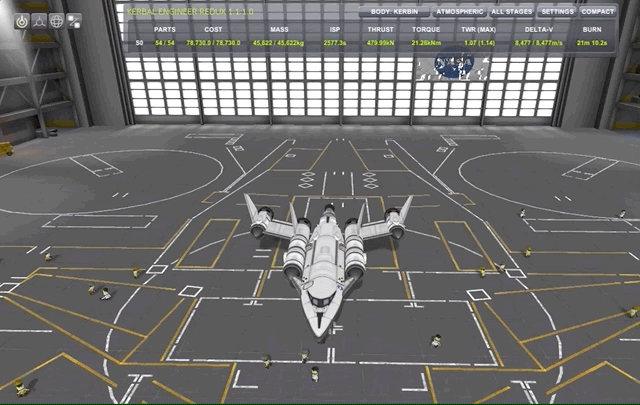
We do not want to simply calculate orbits, we want some actual space ship with propulsion systems in the orbit so we can see the impact of our maneuvers live. For this purpose, I created already in endless hours a huge garage of different more or less efficient vessels for exploring the KSP universe.
For this particular, I will be using my rather tiny SSTO SlickOrbiter consisting of 4 rapier engines which are hybrid engines with both air-breathing and liquid fuel modes. This I complement with an Atomic Rocket Motor engine for space maneuvers with far lower thrust but much higher efficiency (\(I_{SP}\)). I will definitely dedicate a couple of posts to propulsion systems, staging modes etc in a later time, for know just take it as it is.
Spacecraft orientation
Now before we perform and orbit maneuvers or burns, we need to agree on the different directions we can point our spacecraft and perform these burns. Naturally, since we are in 3-dimensional space, we have 3 axis along which we can orient ourselves, each axis having 2 directions.
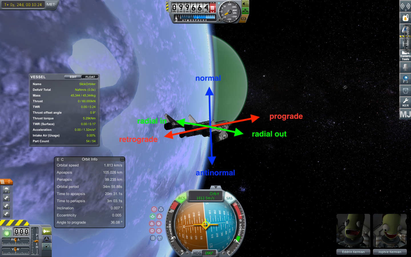
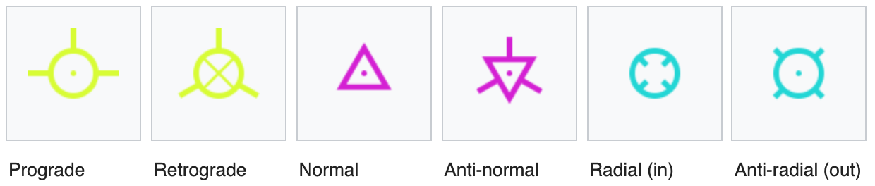
Prograde and retrograde
These vectors run along the axis in which direction the spacecraft is moving along its orbit.
Normal and anti-normal
The normal vectors are perpendicular to the orbital plane.
Radial in and radial out
These vectors are parallel to the orbital plane, and perpendicular to the prograde vector. The radial (or radial-in) vector points inside the orbit, towards the focus of the orbit, while the anti-radial (or radial-out) vector points outside the orbit, away from the body.
Orbital maneuvers
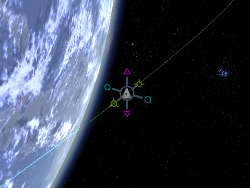
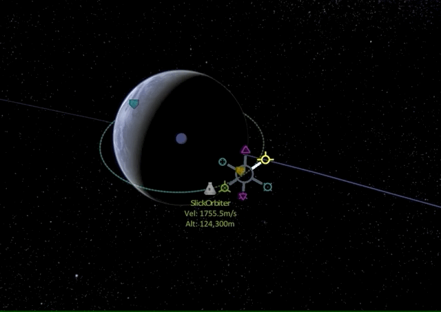
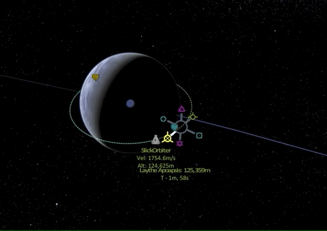
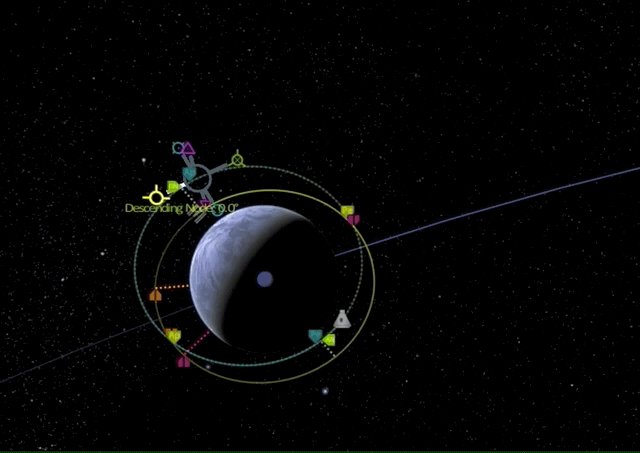
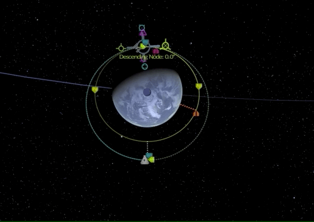
Ok now it is time to make a couple of burns into these directions and see how it affects our orbital parameters. To this end we set up maneuver nodes with directional indicators as shown below.
I will go into more detail and Math about energy efficiency for those individual maneuvers in a later post, this should now only give you a first glimpse and general understanding of how to move around in space.
Prograde and retrograde maneuvers
So we are at the apoapsis of our nearly circular orbit perfectly aligned with the equatorial plane (0 degrees inclination). Let’s see what happens if we burn into prograde direction.
As we can see, the apoapsis moves to the opposite end of our now elliptic orbit and we raised the orbit’s altitude on the opposite side.
What if we do a retrograde burn?
As we can see, the periapsis on the opposing side is lowered until we go suborbital, meaning the spacecraft will deorbit on its way to periapsis and either burn up in the atmosphere or crash on the planet (unless a proper landing procedure is initiated).
In summary, burning prograde will increase orbital velocity, raising the altitude of the orbit on the other side, while burning retrograde will decrease velocity and reduce the orbit altitude on the other side.
This is the most efficient way to change the orbital shape (specifically the most common case, raising or lowering apsides) so whenever possible these vectors should be used.
Normal and anti-normal maneuvers
Again we are at the apoapsis of our nearly circular orbit perfectly aligned with the equatorial plane (0 degrees inclination). Let’s see what happens if we burn into normal direction.
We see that the orbital inclination (the angle between the orbital and equatorial plane) changes.
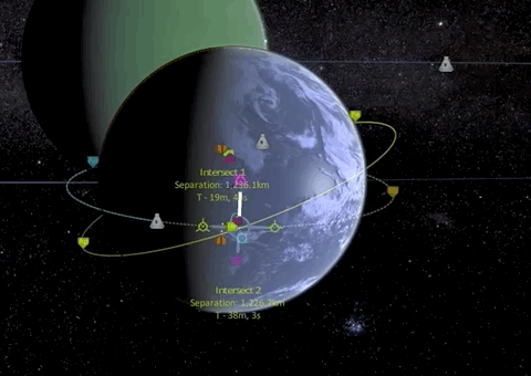
These vectors are generally used to match the orbital inclination of another celestial body or craft, and the only time this is possible is when the current craft’s orbit intersects the orbital plane of the target - at the ascending and descending nodes. We will get to this in a second.
Radial in and radial out maneuvers
One last time we are at the apoapsis of our nearly circular orbit perfectly aligned with the equatorial plane (0 degrees inclination). Let’s see what happens if we burn into the radial out direction.
We see that the orbit start rotating around the craft like spinning a hula hoop with a stick. Radial burns are usually not an efficient way of adjusting one’s path - it is generally more effective to use prograde and retrograde burns.
Orbital insertion
Now let’s combine all those basic orbital maneuvers of the previous section: All the maneuvers we experimented with in the last section are generally described (if sufficient change of the orbital parameters is achieved) as orbit insertion which is a general term for a maneuver that is more than a small correction. It may be used for a maneuver to change a transfer orbit or an ascent orbit into a stable one, but also to change a stable orbit into a descent. Also the term orbit injection is used - which I find even cooler - especially for changing a stable orbit into a transfer orbit, e.g. trans-lunar injection (TLI), trans-Mars injection (TMI) and trans-Earth injection (TEI).
Stable orbits have been described in the previous post, but now we want to specifically look at transfer orbits which enable us to put satellites into orbits, travel to the moon and Mars and all the fancy wonderous places in our solar system and beyond.
So what is a transfer orbit: In orbital mechanics a transfer orbit is an intermediate elliptical orbit that is used to move a satellite or other object from one circular, or largely circular, orbit to another.
There are several types of transfer orbits, which vary in their energy efficiency and speed of transfer and I will quickly go over the most famous ones.
Again, I will go into more detail and Math about energy efficiency for those transfer orbits in a later post, this should now only give you a first glimpse and general understanding of how these orbital insertions work.
Hohmann transfer
In orbital mechanics, the Hohmann transfer orbit is an elliptical orbit used to transfer between two circular orbits of different radii around the same body in the same plane. The Hohmann transfer orbit uses the lowest possible amount of energy in traveling between these orbits.
The term is also used to refer to transfer orbits between different bodies (planets, moons etc.).
A Hohmann transfer requires that the starting and destination points be at particular locations in their orbits relative to each other. Space missions using a Hohmann transfer must wait for this required alignment to occur, which opens a so-called launch window. For a space mission between Earth and Mars, for example, these launch windows occur every 26 months. A Hohmann transfer orbit also determines a fixed time required to travel between the starting and destination points; for an Earth-Mars journey this travel time is about 9 months.

The image shows a Hohmann transfer orbit to bring a spacecraft from a lower circular orbit into a higher one. It is one half of an elliptic orbit that touches both the lower circular orbit the spacecraft wishes to leave (green and labeled 1 on diagram) and the higher circular orbit that it wishes to reach (red and labeled 3 on diagram). The transfer (yellow and labeled 2 on diagram) is initiated by firing the spacecraft’s engine to accelerate prograde so that it will follow the elliptical orbit. This adds energy to the spacecraft’s orbit. When the spacecraft has reached its destination orbit, its orbital speed (and hence its orbital energy) must be increased again to change the elliptic orbit to the larger circular one which is termed circularization.
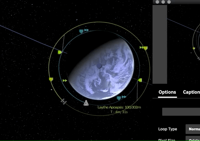
Now let’s do this in KSP. To simplify everything, assume both our starting orbit and our target orbit are already circular. Let’s say we want to reach some space station orbiting Laythe at 250k km and our SlickOrbiter is in a stable orbit at 100k km.
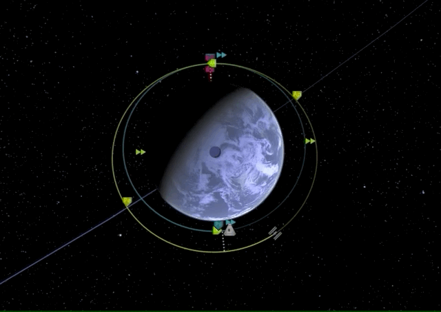
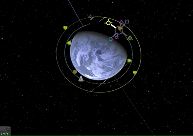
The first thing we have to do is match orbit inclination which is best done by a normal burn at the ascending node.
Now that our orbital planes are synchronized, we can start with our first prograde burn of the Hohmann transfer maneuver which is raising our apoapsis to the target orbit height, effectively transforming our circular orbit into an elliptic orbit.
Now once we have reached our transfer orbit’s apoapsis, we can circularize and match our target orbit by another prograde burn.
There it is, we have performed our first Hohmann transfer.
Bi-elliptic transfer
The bi-elliptic transfer consists of two half-elliptic orbits may, in certain situations, require less energy than a Hohmann transfer maneuver.

From the initial orbit, a first prograde burn (1) boosts the spacecraft into the first transfer orbit with an apoapsis at some point away from the central body. At this point a second prograde burn (2) sends the spacecraft into the second elliptical orbit with periapsis at the radius of the final desired orbit, where a third retrograde burn (3) is performed, injecting the spacecraft into the desired orbit.
While they require one more engine burn than a Hohmann transfer and generally requires a greater travel time, some bi-elliptic transfers require a lower amount of energy than a Hohmann transfer when the ratio of final to initial semi-major axis is 11.94 or greater, depending on the intermediate semi-major axis chosen.
Now let’s do this in KSP. To simplify everything, assume both our starting orbit and our target orbit are already circular and our orbital inclinations are already matched. Again, we want to reach some space station orbiting Laythe at 250k km and our SlickOrbiter is in a stable orbit at 100k km.
We will first raise our apoapsis above the target orbit to create an elliptic orbit with a long prograde burn.
Now we wait until we have reached the new apoapsis for another prograde burn to raise our periapsis to the level of the target orbit.
Finally, we perform a retrograde burn at the new periapsis to lower our apoapsis for circularizing our target orbit.
There it is, we have performed our first Bi-elliptic transfer.
Now that you have a basic overview of spacecraft orientation, burns into those directions and their impact on the spacecrafts orbit, as well as how to combined those maneuvers into orbit insertions, we can have laid the foundation to dive deeper into energy efficiency of those maneuvers, the famous delta-v and the Rocket equation in a later post. Until then - godspeed.